Hello Friends! Today, we will cover all possible things about what is centre tapped full wave rectifier circuit diagram and their working operations with ease. Making ensure that after reading this post; you will definitely fully aware about Centre Tapped Full Wave Rectifier without any issue.
What is Center Tapped Full Wave Rectifier?
Center-Tapped Full Wave Rectifier is used in electronics that helps to convert the alternating current (AC) to direct current (DC). It also employs the center-tapped transformer, and dividing the secondary winding into two halves. During each half-cycle of the AC input, the diodes conduct in alternate directions, allowing both halves of the transformer secondary to contribute to the output.
This results in a more efficient use of the transformer, producing a pulsating DC output with reduced ripple. The center-tap allows for a dual polarity output, enhancing its application in various power supply and electronic systems.
Article Hot Headlines:
In this section, we will show you all headlines about this entire article; you can check them as your choice; below shown all:
What is Center Tapped Full Wave Rectifier?
Centre Tap Full Wave Rectifier Circuit
Working of Center-Tapped Full Wave Rectifier
Difference between Center Tapped Vs Bridge Rectifier FWR
Characteristics of Center-Tapped Full Wave Rectifier
Center Tapped Full Wave Rectifier Applications
Advantages of Center Tapped Full Wave Rectifier
Disadvantages of Center Tapped Full Wave Rectifier
FAQs (Frequently Asked Questions)
What is the output frequency of a center-tapped full-wave rectifier?
What is the ripple frequency in center-tapped full-wave rectifier?
How is the efficiency of center-tapped full-wave rectifier calculated?
What is the peak output voltage of center-tapped full wave rectifier?
Why is a capacitor used in center-tapped full wave rectifier circuit?
What is the formula for center-tapped full wave rectifier?
What is the formula for center-tapped full wave rectifier?
Let’s Get Started!!
Centre Tap Full Wave Rectifier Circuit
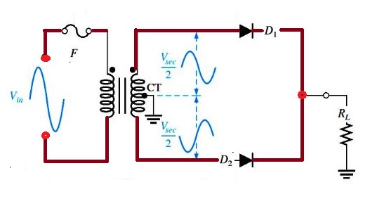
Center-tapped full wave rectifier employs the center-tapped transformer and two diodes that help to convert the complete AC signal into a DC signal. It is made up of an AC source, a center-tapped transformer, two diodes, and a load resistor. The center tap is generally considered as the ground point or the zero voltage reference point.
During the positive half cycle of the input AC signal, one diode conducts, and during the negative half cycle, the other diode conducts, allowing both halves of the AC waveform to be used. This result in a higher DC output compared to a half-wave rectifier.
Working Principle of Center-Tapped Full Wave Rectifier
Here’s a step-by-step explanation of the working principle of a center-tapped full-wave rectifier:
Center Tapped Full Wave Rectifier Operations
Center-Tapped Transformer: The rectifier circuit begins with a center-tapped transformer. The secondary winding of the transformer has a center tap, which is a connection at the midpoint of the winding. The primary winding is connected to the AC power source.
AC Input: The AC voltage is applied across the primary winding of the transformer. As the AC voltage alternates, it induces an alternating voltage in the secondary winding.
Center Tapping: The center tap of the secondary winding is connected to the ground or reference point. This creates two equal and out-of-phase AC voltages across the two halves of the secondary winding.
Diode Bridge: Two diodes, usually connected in a bridge configuration, are used to rectify the AC voltage. The diodes are connected to the ends of each half of the secondary winding.
Output: The load is connected between the common point of the two diodes (output terminals) and the center tap of the transformer. The load receives a pulsating DC voltage that is effectively the absolute value of the input AC voltage.
Smoothing Filter: While the center-tapped full-wave rectifier produces a pulsating DC output, a smoothing filter, typically a capacitor can be added across the load to reduce the ripple and provide a more stable DC voltage.
Difference between Center Tapped Vs Bridge Rectifier Full Wave Rectifier
Here’s a tabular comparison between the Center-Tapped Full Wave Rectifier and a Bridge Rectifier including:
Characteristics of Center-Tapped Full Wave Rectifier
The center-tapped full-wave rectifier has several characteristics that define its performance and behavior in converting alternating current (AC) to direct current (DC). Here are some key characteristics of a center-tapped full-wave rectifier:
Full-Wave Rectification: The center-tapped full-wave rectifier provides full-wave rectification, meaning that it rectifies both halves of the input AC waveform. This result in a more efficient utilization of the input AC signal compared to half-wave rectification.
Transformer Utilization Factor (TUF):The Transformer Utilization Factor (TUF) is a measure of how effectively the transformer is utilized in transferring power from the primary winding to the secondary winding. For a center-tapped full-wave rectifier, TUF is higher compared to half-wave rectification, indicating better transformer utilization.
Output Frequency: The output frequency of the rectified DC signal is twice the input AC frequency. This is because both the positive and negative halves of the AC cycle are utilized for rectification.
Ripple Frequency:The ripple frequency in the output waveform is twice the input AC frequency. This is a result of the full-wave rectification process, where two rectified pulses occur per AC cycle.
Peak Inverse Voltage (PIV): The peak inverse voltage across each diode in the center-tapped full-wave rectifier is half of the maximum secondary voltage. This leads to lower PIV ratings for the diodes compared to a bridge rectifier, which can be advantageous in terms of diode selection.
Transformer Voltage Rating: The transformer in a center-tapped full-wave rectifier needs to have a higher voltage rating compared to a half-wave rectifier. This is because it must withstand the entire peak voltage of the AC input.
Efficiency: The center-tapped full-wave rectifier is more efficient than a half-wave rectifier but less efficient than a bridge rectifier. The use of both halves of the AC cycle contributes to higher efficiency compared to half-wave rectification.
Filtering Requirements: The rectified output of a center-tapped full-wave rectifier still contains some ripple. To obtain a smoother DC output, filtering elements such as capacitors are often used across the load to reduce the ripple.
Output Waveform: The output waveform is pulsating DC with a higher frequency compared to the input AC waveform. The addition of a smoothing filter, such as a capacitor, can convert the pulsating DC into a more stable DC output.
Center Tapped Full Wave Rectifier Applications
Here are some common applications of center-tapped full-wave rectifiers:
Power Supplies: Center-tapped full-wave rectifiers are commonly used in power supply circuits to convert the AC voltage from the mains into a more stable DC voltage for electronic devices. The rectified output is then smoothed using filters, such as capacitors, to reduce the ripple and provide a relatively steady DC voltage.
Battery Chargers: These rectifiers can be used in battery charging circuits where a stable DC voltage is required to charge batteries efficiently. The rectified DC output can be further regulated to achieve the desired charging voltage.
Audio Amplifiers: In audio applications, center-tapped full-wave rectifiers are used to convert the AC signal from a transformer to a pulsating DC signal, which can be further filtered and regulated for use in amplifier circuits. This helps in providing a stable DC bias for amplifying audio signals.
DC Motor Drives: DC motors often require a steady DC voltage for proper operation. Center-tapped full-wave rectifiers can be used in motor drive circuits to convert AC power to a pulsating DC power source for driving DC motors.
Testing and Measurement Equipment: Various electronic testing and measurement equipment require a stable and well-regulated DC power supply. Center-tapped full-wave rectifiers, followed by filtering and voltage regulation, can be used to provide the required DC voltage for such applications.
Industrial Applications: In industrial settings, where controlled DC power is needed for various processes, center-tapped full-wave rectifiers can be employed as part of the power supply system to convert AC power from the grid into a suitable form.
Advantages of Center Tapped Full Wave Rectifier
There are some common advantages of center-tapped full wave rectifier include:
Utilizes both halves of the AC input cycle, leading to higher efficiency compared to half-wave rectifiers
Produces a smoother DC output with lower ripple compared to half-wave rectifiers, resulting in better filtering and improved performance.
TUF is higher as the transformer is used more effectively, making better use of the input power.
Requires a transformer with a lower rating compared to a full-wave bridge rectifier for the same output power, which can lead to cost savings.
Provides better voltage regulation due to reduced ripple and improved filtering
Transformer design is relatively simpler compared to full-wave bridge rectifiers, making it cost-effective and easier to implement.
Diodes in a center-tapped full-wave rectifier have a lower peak inverse voltage (PIV) compared to those in a half-wave rectifier, leading to increased reliability and longer diode life.
Generates a symmetrical output waveform, making it suitable for applications where a balanced DC voltage is required.
Ideal for applications with lower power requirements, as it provides a good balance between efficiency and simplicity.
Generally more cost-effective than full-wave bridge rectifiers, especially in lower power applications.
Disadvantages of Center Tapped Full Wave Rectifier
Here are the disadvantages of Center Tapped Full Wave Rectifier like as:
Efficiency decreases at higher frequencies, making it less suitable for applications where high-frequency rectification is required.
Requires a larger and heavier transformer compared to a half-wave rectifier, especially when compared to modern alternatives like bridge rectifiers.
The transformer used in a center-tapped full-wave rectifier may be more expensive due to its larger size and specifications.
Only half of the transformer secondary winding is used during each half-cycle, resulting in underutilization and increased cost.
Transformer design can be more complex compared to a half-wave rectifier, which may add to the overall system cost.
TUF is lower compared to a full-wave bridge rectifier, affecting the overall efficiency and performance.
Not well-suited for high-voltage applications due to limitations in transformer design and increased stress on diodes.
Necessitates a specific type of transformer with a center-tapped secondary winding, limiting transformer options
May not be suitable for high-power applications due to the limitations of diode ratings and transformer design
The ripple factor is higher compared to a full-wave bridge rectifier, affecting the quality of the DC output.
FAQs (Frequently Asked Questions)
What is the output frequency of a center-tapped full-wave rectifier?
The output frequency of a center-tapped full-wave rectifier is the same as the input frequency. It does not alter the frequency; it only rectifies the waveform.
What is the ripple frequency in center-tapped full-wave rectifier?
The ripple frequency in a center-tapped full-wave rectifier is twice the input frequency. This is because both halves of the AC waveform are rectified, effectively doubling the frequency of the ripples in the output.
How is the efficiency of center-tapped full-wave rectifier calculated?
The efficiency of a center-tapped full-wave rectifier is calculated by dividing the DC power at the load by the AC power supplied by the transformer. It is typically expressed as a percentage. The formula is: Efficiency (%) = (DC power output / AC power input) * 100.
What is the peak output voltage of center-tapped full wave rectifier?
The peak output voltage of a center-tapped full wave rectifier is only equal to half of the peak input voltage.
Why is a capacitor used in center-tapped full wave rectifier circuit?
The filter capacitor is used to smooth out the DC output by reducing the ripple. It stores charge during the peaks of the rectified waveform and releases it during the troughs, providing a more constant DC voltage.
What is the formula for center-tapped full wave rectifier?
The main formula associated with a center-tapped full-wave rectifier is the average DC output voltage (VDC).
The average DC output voltage for a center-tapped full-wave rectifier is given by:
VDC = 2×Vmax/π
Where:
VDC is the average DC output voltage,
Vmax is the maximum voltage of one half of the secondary winding of the center-tapped transformer.
This formula assumes ideal conditions and no load resistance. In practice, the presence of a load resistor and other factors may affect the actual output voltage.
What is Centre tapped transformer full wave rectifier?
Center-tapped transformer full-wave rectifier converts alternating current to direct current by using the center-tapped transformer and two diodes. It rectifies both halves of the AC waveform, enhancing efficiency in low to moderate power applications like electronic devices and battery chargers.
Final Words
Through this article; you have been completed learnt about what is centre tapped full wave rectifier circuit diagram and their working operations with ease. If this post is giving value you, then please share it along with your friends, family members or relatives over social media platforms like as Facebook, Instagram, Linked In, Twitter, and more.


 with Block Diagram")

 | Working of SRAM")
