Hello Learner! Today, from this article, we will explain all possible things about what is full wave rectifier with its circuit diagram; involving with working operation of full wave rectifier with their types and formula with ease. This is ultimate content over the internet; make ensure that after reading this article; you will definitely completely understand about Full Wave Rectifier without getting any hassle.
What is Full Wave Rectifier?
Definition: Full Wave Rectifier is an electronic circuit that allow converting the alternating current (AC) into direct current (DC). Unlike half-wave rectifiers; it implements both halves of the AC waveform, making ensure the more continuous flow of current. This is typically achieved through a configuration of diodes that allow the positive and negative cycles of the AC signal to be rectified.
The result is a smoother DC output with decreased ripple, making it suitable for several applications, like as power supplies and electronics. Full Wave Rectifiers improve the efficiency with maximizing the use of the AC input waveform that is providing the more consistent DC output.
Full Wave Rectifier Tutorial Headlines:
In this section, we will show you all headlines about this entire article; you can check them as your choice; below shown all:
What is Full Wave Rectifier?
Full Wave Rectifier Circuit
How Does Full Wave Rectifier Work?
Types of Full Wave Rectifier
Centre-Tapped Full Wave Rectifier
Bridge Full Wave Rectifier
Full Wave Rectifier Characteristics
Difference between Half-Wave and Full-Wave Rectifier
Ripple Factor of Full Wave Rectifier
Full-Wave Rectifier Formulas
FAQs (Frequently Asked Questions)
What is the working principle of full wave rectifier?
What are the key components of full-wave rectifier circuit?
Why full wave rectifier is used?
What is the role of smoothing capacitor in full-wave rectifier circuit?
What are different types of full wave rectifier with diagram?
What is the operation of three phase full wave rectifier?
Let’s Get Started!!
Full Wave Rectifier Circuit
Full-wave rectifier is an electric circuit that helps to convert both half cycles of an alternating current (AC) into direct current (DC). These circuits are made either using multiple diodes or using diodes and a transformer. The main components of full-wave rectifier circuit include:
Input AC Signal: The full-wave rectifier starts with an alternating current (AC) input signal. This signal is usually in the form of a sinusoidal waveform.
Diode Bridge: In a full-wave rectifier, four diodes are arranged in a bridge configuration. The bridge rectifier allows current to flow through the load in one direction during both halves of the AC cycle.
Positive Half-Cycle: During the positive half-cycle of the AC input, two diodes become forward-biased, allowing current to flow through the load in a specific direction. The other two diodes are reverse-biased and block the current flow in the opposite direction.
Negative Half-Cycle: As the AC waveform enters the negative half-cycle, the roles of the diodes switch. The previously reverse-biased diodes become forward-biased, and vice versa. This allows current to flow through the load in the same direction as it did during the positive half-cycle.
Output: The result is a continuous flow of current in the same direction through the load during both halves of the AC cycle. The output across the load resistor is a pulsating direct current (DC) waveform.
Smoothing (Optional): To obtain a smoother DC output; capacitor is often connected in parallel with the load resistor. This capacitor helps reduce the ripple or variations in the output voltage.
DC Output: The final output across the load resistor is a relatively smooth DC voltage that has been rectified from the original AC input.
Types of Full Wave Rectifier
There are two commonly types of full wave rectifiers, like as the center-tapped full-wave rectifier and the bridge rectifier. They are effectively capable to convert AC signals into DC output voltages; both types have different circuit configurations and characteristics.
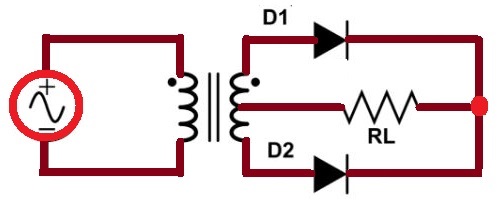
Centre-Tapped Full Wave Rectifier
Center tapped full-wave rectifier is a kind of rectifier circuit that is used in power supply applications to convert alternating current (AC) into direct current (DC). The center-tapped full-wave rectifier is an improvement over the simple full-wave rectifier that helping out to provide the higher efficiency and decrease the ripple in the output.
Here’s how a center-tapped full-wave rectifier works:
Transformer: The input to the rectifier is typically through a transformer. The primary winding of the transformer is connected to the AC supply, and the secondary winding has a center tap. The center tap serves as a reference point, dividing the secondary winding into two equal halves.
Diodes: Two diodes are connected in a bridge configuration, forming a bridge rectifier. The anodes of the diodes are connected to the ends of the secondary winding, and the cathodes are connected together.
Operation: During the positive half-cycle of the AC input voltage, the upper end of the secondary winding becomes positive with respect to the center tap. This forward-bias is one of the diodes that are allowing the current to flow through it. Simultaneously, the lower end of the secondary winding becomes negative, reverse-biasing the other diode, preventing current flow through it.
During the negative half-cycle of the AC input voltage, the polarities reverse. Now, the lower end of the secondary winding becomes positive, forward-biasing the second diode, while the upper end becomes negative, reverse-biasing the first diode.
Output:As a result, current flows through the load during both half-cycles of the AC input, creating a pulsating DC output. The center tap is often connected to the ground, and the DC output is taken from the common point of the diodes.
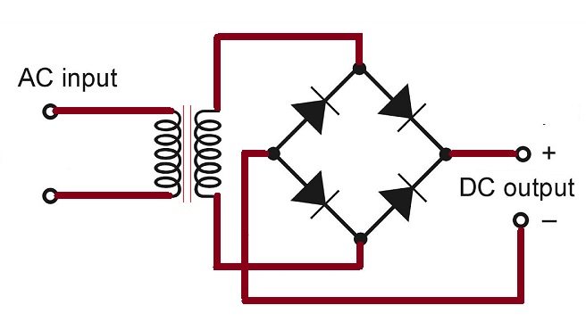
Bridge Rectifier
Bridge rectifier is also known as the full wave bridge rectifier; it is a type of rectifier circuit that is used to convert alternating current (AC) into direct current (DC). It is widely used in power supply applications due to its efficiency and simplicity. The bridge rectifier configuration uses four diodes connected in a bridge arrangement, and it doesn’t require a center-tapped transformer.
Here’s how a bridge rectifier works:
Diodes Configuration: Four diodes (labeled D1, D2, D3, and D4) are arranged in a bridge configuration. The AC input is applied across the diode bridge.
Operation:During the positive half-cycle of the AC input voltage, the voltage at terminal A (relative to terminal C) is higher than at terminal B. Diodes D1 and D2 become forward-biased, allowing current to flow through D1 and D2.
Simultaneously, diodes D3 and D4 become reverse-biased, preventing current flow through them.
During the negative half-cycle of the AC input voltage, the polarities reverse. Now, terminal B is at a higher voltage than terminal A. Diodes D3 and D4 become forward-biased, allowing current to flow through D3 and D4, while D1 and D2 become reverse-biased.
Output: As a result, current flows through the load during both half-cycles of the AC input, creating a pulsating DC output. The DC output is taken across the load connected between the points where D1 and D2 meet and where D3 and D4 meet.
Full Wave Rectifier Characteristics
There are several characteristics of full wave rectifier, including:
Efficiency: Around 81.2%, higher than half-wave rectifiers.
Peak Current: Higher peak current compared to half-wave rectifiers.
Filtering: Capacitor filtering is often employed to smooth the pulsating DC output.
Load Resistance: Influences output voltage and current, higher resistance leads to higher DC voltage but lower DC current.
Difference between Half-Wave and Full-Wave Rectifier
Here is a comparison between Half-Wave and Full-Wave Rectifiers in tabular form:
Parameter
Half-Wave Rectifier
Full-Wave Rectifier
Conducting Angle
180 degrees (π radians)
360 degrees (2π radians)
Number of diodes used
1
2 or 4 depending on the type of circuit
Form factor
1.57
1.11
Rectifier efficiency
40.6%
81.2%
Ripple factor
Higher
Lower
Cost
Lower
Higher
Ripple Factor of Full Wave Rectifier
The ripple factor is a measure of the AC component or the “ripple” in the output of a rectifier circuit. It quantifies how much the DC output of the rectifier deviates from a pure DC voltage. For a full-wave rectifier, the ripple factor is given by the formula:
Ripple Factor = √V2rms-V2dc /Vdc
Where:
Vrms is the root mean square value of the AC component of the output voltage.
Vdc is the DC component of the output voltage.
For a full-wave rectifier, the RMS value of the AC component can be calculated as:
Vrms=Vm/2√2
Where:
Vm is the maximum voltage of the secondary winding.
The DC component Vdc is equal to the average value of the rectified voltage. For a full-wave rectifier, this can be calculated as:
Vdc=2Vm/ π
Substituting these values into the ripple factor formula, you can calculate the ripple factor for a full-wave rectifier. Keep in mind that a lower ripple factor indicates a smoother DC output.
It’s worth noting that if you assume ideal conditions and neglect the transformer and diode losses, the ripple factor for a full-wave rectifier is approximately 0.48.
Full-Wave Rectifier Formulas
Peak Inverse Voltage
The Peak Inverse Voltage (PIV) is the maximum voltage that appears across the diode in a rectifier circuit when it is in the reverse-bias condition. For a full-wave rectifier, the PIV occurs when the diode is reverse-biased during the portion of the AC cycle when the diode is not conducting.
In a full-wave rectifier, the PIV can be calculated using the formula:
PIV=2⋅Vm
Where:
PIV is the Peak Inverse Voltage.
Vm is the peak voltage of the input AC waveform.
RMS Value of Current
In a full-wave rectifier, the RMS (Root Mean Square) value of the output current can be calculated using the formula:
Irms= Im /√2
Where:
Irms is the root mean square value of the current.
Im is the maximum or peak value of the current.
DC Output Voltage
The DC (direct current) output voltage of a full-wave rectifier can be calculated using the formula:
VDC=2 √2⋅Vmax/π
Where:
VDC is the DC output voltage.
Vmax is the maximum or peak voltage of the input AC waveform.
Efficiency of Full-Wave Rectifier
The efficiency (η) of a full-wave rectifier can be calculated using the following formula:
η=PDC/PAC
Where:
η is the efficiency.
PDC is the DC power delivered to the load.
PAC is the AC power drawn from the source.
The formula for PDC is given by:
PDC=IDC⋅VDC
Where:
IDC is the average DC current.
VDC is the DC voltage across the load.
The formula for PAC is given by:
PAC=Irms⋅Vrms
Where:
Irms is the RMS current.
Vrms is the RMS voltage of the input AC waveform.
Form Factor
The form factor (F.F.) of a waveform is the ratio of its root mean square (RMS) value to its average (or mean) value. For a full-wave rectified waveform, the form factor can be calculated using the formula:
Form Factor (F.F.) = Vrms/Vavg
Where:
Vrms is the RMS voltage of the waveform.
Vavg is the average (or mean) voltage of the waveform.
Peak Factor
The peak factor (also known as the peak-to-average ratio) of a waveform is the ratio of its peak value to its RMS (Root Mean Square) value. For a full-wave rectified waveform, the peak factor can be calculated using the formula:
Peak Factor= Vm/Vrms
Where:
Vm is the peak voltage of the waveform.
Vrms is the RMS voltage of the waveform.
FAQs (Frequently Asked Questions)
What is the working principle of full wave rectifier?
Full-wave rectifier converts alternating current (AC) to direct current (DC) by using diodes to allow the flow of current in both positive and negative halves of the AC cycle, resulting in a more continuous and smoother DC output.
What are the key components of full-wave rectifier circuit?
The main components of full-wave rectifier circuit include diodes, a transformer (for center-tap rectifiers), and load resistor. In a bridge rectifier, four diodes are arranged in bridge configuration.
Why full wave rectifier is used?
Full-wave rectifiers are used because they offer several advantages over half-wave rectifiers, such as higher efficiency, smoother output waveforms, and the ability to utilize both halves of the AC cycle. Their essential components are used in several electronic applications, like as power supplies, battery charging systems, signal processing circuits, and mobile phones.
What is the role of a smoothing capacitor in a full-wave rectifier circuit?
Smoothing capacitor is often added to the full-wave rectifier circuit to decrease the ripple in the DC output. It helps in smoothing out the variations in voltage, producing the more stable DC output for attached devices.
What are different types of full wave rectifier with diagram?
Full wave rectifier is classified into two different categories, including centre-tapped full wave rectifier and full-wave bridge rectifier. Above in this article, we already have been explained with their suitable circuit diagram; you can check them.
What is the operation of three phase full wave rectifier?
Three-phase full-wave rectifier operates by using two half-wave rectifier circuits, which produce a lower ripple output than a half-wave rectifier. It utilizes two diodes per phase and can be fed by a star or delta connected transformer supply.
Closure
Through this blog post; you have been fully educated about what is full wave rectifier with its circuit diagram; involving with working operation of full wave rectifier with their types and formula with ease. If this article is useful for you, then please share it along with your friends, family members or relatives over social media platforms like as Facebook, Instagram, Linked In, Twitter, and more.

 Full Wave Rectifier Circuit Diagram


 - Easiest Guide")
 | Working of SRAM")


