Hello Friends! Today, we are going to cover all possible things about what is full wave bridge rectifier; involving its circuit diagram along with their working operations and types with ease. This is unique article over the internet; so making ensure that at the end of this post; you will definitely completely understand about Full Wave Bridge Rectifier without getting any hindrance.
What is Bridge Rectifier?
Bridge rectifier is type of full wave rectifier that converts an AC signal into a DC signal by using the four or more diodes arranged in a bridge circuit configuration. The input signal get apply across two terminals, then output DC signal achieved across a load resistor connected between two other terminals.
Bridge Full Wave Rectifier Diagram
The bridge rectifier provides full-wave rectification that means that it helps to convert the input waveform to one of constant polarity. This configuration is the absence of the expensive center-tapped transformer, which reduces the size and cost of the circuit. The bridge rectifier is the most efficient rectifier circuit.
Bridge Rectifier Tutorial Headlines:
In this section, we will show you all headlines about this entire article; you can check them as your choice; below shown all:
What is Bridge Rectifier?
Bridge Rectifier Circuit Construction
Bridge Rectifier Working Principle with Operations
Characteristics of Bridge Rectifier
Types of Bridge Rectifiers
Applications of Bridge Rectifiers
Advantages of Bridge Rectifiers
Disadvantages of Bridge Rectifier
FAQs (Frequently Asked Questions)
What is Full Wave Bridge Rectifier (FWBR) and its types?
What is the ripple factor in a Full Wave Bridge Rectifier?
How is the output voltage calculated in Full Wave Bridge Rectifier?
Can Full Wave Bridge Rectifiers be used for high voltage applications?
What is the difference between a Full Wave Bridge Rectifier and a Center-Tap Full Wave Rectifier?
How can the efficiency of a Full Wave Bridge Rectifier be improved?
Let’s Get Started!!
Bridge Rectifier Circuit Construction
Here, we will guide you step-by-step on constructing a bridge rectifier circuit:
Transformer with secondary winding that provides the desired AC voltage
Load resistor (optional, for testing purposes)
Capacitor (optional, for smoothing the DC output)
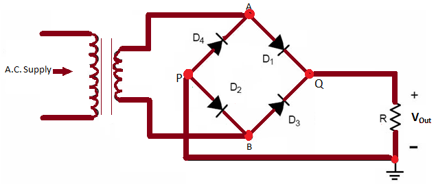
Bridge Rectifier Circuit Diagram
Construction Phases
Identify the Transformer Leads: The transformer should have a primary winding and a secondary winding. The primary winding connected to the AC power source, and the secondary winding provides the AC output that you want to rectify. Identify the leads of the secondary winding.
Diode Placement: Place four diodes in a bridge configuration. The bridge configuration consists of four arms, with each arm containing one diode. The diodes should form a square or diamond shape. Label the diodes as D1, D2, D3, and D4. The cathode of each diode (indicated by a band or line) should point towards the center of the bridge.
Connect the Transformer: Connect the ends of the secondary winding to the AC input of the bridge rectifier. It connects one end to the junction of D1 and D2 and the other end to the junction of D3 and D4.
Connect the DC Load (Optional): Connect a load resistor (e.g., a resistor or an LED with an appropriate resistor in series) across the DC output terminals of the bridge rectifier. This provides a load to test the rectification.
Optional Smoothing Capacitor: If you want to smooth the DC output, you can connect a capacitor across the DC output terminals. This capacitor will help reduce the ripple in the DC waveform.
Final Connections: Connect the other ends of D1 and D3 (anodes) to the positive DC output terminal. Connect the other ends of D2 and D4 (anodes) to the negative DC output terminal.
Testing: Test the circuit with the AC power source. Verify the DC output using a multi-meter. Check for the correct polarity and smoothness of the DC waveform.
Bridge Rectifier Working Principle
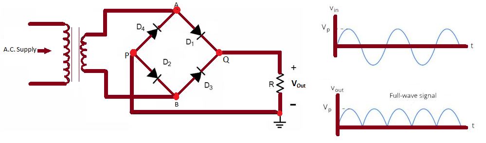
The key working principle of a bridge rectifier lies in its ability to allow the flow of current in one direction, effectively converting the negative half-cycles of the AC input into positive half-cycles. Here’s how the bridge rectifier works:
The bridge rectifier circuit typically connected to the secondary winding of a transformer, which provides an alternating voltage.
Diode Configuration:
The four diodes in the bridge rectifier labeled as D1, D2, D3, and D4. These diodes get arrange in a bridge configuration, forming a square or diamond shape.
The cathode of each diode (usually indicated by a band or line on the diode) points towards the center of the bridge, and the anode points away from the center.
Positive Half-Cycle:
During the positive half-cycle of the AC input, the voltage at the secondary winding causes diodes D1 and D2 to become forward-biased, allowing current to flow through them.
Simultaneously, diodes D3 and D4 become reverse-biased, preventing current flow through them.
Negative Half-Cycle:
During the negative half-cycle of the AC input, the voltage at the secondary winding causes diodes D3 and D4 to become forward-biased, allowing current to flow through them.
At the same time, diodes D1 and D2 become reverse-biased, blocking current flow through them.
DC Output:
As a result of the diode configuration, the output at the load (connected to the output terminals) only experiences the positive half-cycles of the AC input. The negative half-cycles are effectively blocked.
The output voltage across the load resistor or device is now a pulsating DC waveform, consisting of the positive peaks of the original AC waveform.
Characteristics of Bridge Rectifier
Here, some remarkable characteristics of a bridge rectifier include:
Ripple Factor: The output DC signal’s smoothness described by the ripple factor, which is the ratio of ripple voltage to pure DC voltage. A bridge rectifier has a ripple factor of 0.48.
Efficiency: The efficiency of a bridge rectifier is the ratio of the DC output power to the AC input power. It has maximum rectifier efficiency is 81.2%.
Peak Inverse Voltage: This is the maximum voltage the rectifier can attain in reverse bias without conducting. For a bridge rectifier, the peak inverse voltage is Vm, which is half of that of a center-tap rectifier.
Transformer Utilization Factor (TUF): The TUF of a bridge rectifier higher compared to a half-wave rectifier. TUF is a measure of how effectively the transformer utilized in delivering power to the load.
Smoothness of DC Output: The DC output signal of a bridge rectifier is smoother than that of a half-wave rectifier, as it allows the electric current to flow during both positive half cycles and negative half cycles of the flowing input AC signal.
Types of Bridge Rectifiers
Bridge rectifiers are classified into four different categories as per their operations and characteristics, including:
Single Phase Bridge Rectifier
This is suitable for applications where the input AC voltage is a single-phase.
It employs the 4 diodes that arranged in a bridge configuration.
The diodes connected in such a way that they form two series paths through which the current can flow, allowing for the conversion of AC to DC.
Three-Phase Bridge Rectifier
This bridge rectifier uses when the input AC voltage is three-phase.
It consists of six diodes arranged in a bridge configuration.
The three-phase bridge rectifier provides a smoother DC output compared to the single-phase bridge rectifier.
Uncontrolled Bridge Rectifier
This rectifier uses four diodes to form a closed-loop bridge.
It does not require a center tap over the secondary winding of the transformer
AC components in the rectified output are called ripples.
Ripple Factor defines as the percentage of AC components (or ripples) in the rectified DC output.
To reduce the ripple factor, a filter capacitor uses at the output.
Controlled Bridge Rectifier
Utilizes diodes and thyristors (SCRs) to control the output voltage
Allows for the regulation of the output DC voltage
Offers improved efficiency and control over uncontrolled bridge rectifiers
Enables the adjustment of the firing angle to regulate the output voltage
These applications are commonly using where variable DC voltage required, such as in motor speed control and heating applications
Applications of Bridge Rectifiers
Here are some common applications of bridge rectifiers:
Power Supplies: Bridge rectifiers are commonly using in power supplies for electronic devices. They convert the AC voltage from the mains into DC voltage suitable for powering electronic circuits and devices.
Battery Chargers: Bridge rectifiers use in battery chargers to convert AC power from the electrical grid into DC power for charging batteries. This application is common in automotive, industrial, and consumer electronics.
LED Drivers: Light-emitting diodes (LEDs) require a constant DC voltage for proper operation. Bridge rectifiers can utilise into LED drivers that help to convert AC power to the required DC voltage; and providing a stable power source for LED lighting systems.
DC Motor Drives: DC motors require a steady DC power supply for operation. Bridge rectifiers are also using in motor drives to convert AC power to DC, providing the necessary power to drive the motor.
Audio Amplifiers: Many audio amplifiers use bridge rectifiers to convert the AC power supply to DC, ensuring a stable and constant voltage for amplification circuits.
Radio Frequency (RF) Power Supplies:In RF applications, bridge rectifiers use to convert AC power to DC for powering transmitters, receivers, and other RF equipment.
Welding Power Supplies: Welding machines often use bridge rectifiers to convert AC power from the grid into the high-current DC power required for welding applications.
Uninterruptible Power Supplies (UPS): UPS systems use bridge rectifiers to convert AC power from the mains into DC power to charge internal batteries. In the event of a power outage, the stored DC power then inverted back to AC to provide a continuous power supply to connected devices.
Electronic Devices and Appliances: Many electronic devices and household appliances use bridge rectifiers as part of their power supply circuits to convert AC power to DC for internal components.
Photovoltaic (Solar) Power Systems: In some solar power systems, bridge rectifiers can also use to convert the AC output from solar inverters to DC power for storage in batteries or for direct use in DC loads.
Advantages of Bridge Rectifiers
Bridge rectifiers offer several advantages in electronic circuits where the conversion of alternating current (AC) to direct current (DC required. Here are the top five advantages of bridge rectifiers:
Efficiency: Bridge rectifiers get well- known for their high efficiency in converting AC to DC. The full-wave rectification process used by bridge rectifiers ensures that the entire AC waveform utilized, resulting in a higher average output voltage compared to half-wave rectifiers. This efficiency is crucial in applications where a stable and efficient DC power supply required.
Higher Output Voltage: The full-wave rectification process employed by bridge rectifiers produces a higher average output voltage compared to half-wave rectifiers. This is making to leads a more reliable and higher-voltage DC output that is advantageous in applications needing the stable power supply for all electronic devices.
Smaller Ripple Factor:The ripple factor of a rectifier indicates the amount of AC component present in the rectified output. Bridge rectifiers have a smaller ripple factor compared to half-wave rectifiers, resulting in a smoother and more stable DC output. This is particularly important in applications where a constant and low-ripple DC voltage is essential for proper device operation.
Compact Design: Bridge rectifiers can be implemented in a compact design, making them suitable for applications with space constraints. The arrangement of four diodes in a bridge configuration allows for a compact layout on a circuit board, contributing to the overall miniaturization of electronic devices.
Improved Power Utilization: Bridge rectifiers utilize both halves of the AC input waveform, ensuring better power utilization compared to half-wave rectifiers. The continuous conversion of the AC signal into DC results in a more efficient use of the available power, making bridge rectifiers suitable for applications where maximizing power efficiency is a priority.
Disadvantages of Bridge Rectifier
There are some common drawback and limitations of bridge rectifier, instead of their advantages, including:
Voltage Drop: Bridge rectifiers introduce a voltage drop across the diodes, leading to a reduction in the output voltage. This voltage drop is getting to affect the efficiency of the rectification process and may need the additional components, including voltage regulators, to compensate for the loss.
Harmonic Distortion: The full-wave rectification process used by bridge rectifiers can result in higher harmonic distortion in the output waveform compared to half-wave rectifiers. This harmonic content may introduce unwanted noise in sensitive electronic circuits and radio frequency interference (RFI) in communication systems.
Complexity: Bridge rectifiers consist of four diodes arranged in a specific configuration, making them more complex than the simpler half-wave rectifiers. The additional components can increase the overall cost of the rectification circuit and may require careful design considerations.
Heat Dissipation: Like all diodes, those in a bridge rectifier generate heat during operation. In high-power applications, the cumulative heat dissipation from four diodes can be significant. Adequate heat sinking or cooling mechanisms may be required to prevent overheating and ensure the reliability of the rectifier.
Reverse Recovery Time: Diodes used in bridge rectifiers have a reverse recovery time during which they block the reverse voltage. This can lead to increased switching losses and may limit the speed at which the rectifier can operate effectively. In high-frequency applications, this reverse recovery time becomes more critical.
FAQs (Frequently Asked Questions)
What is Full Wave Bridge Rectifier (FWBR) and its types?
A Full Wave Bridge Rectifier is an electronic circuit that converts alternating current (AC) to direct current (DC). It utilizes a bridge arrangement of diodes to rectify the full cycle of AC input. This bridge rectifier has four different variants, above shown each one.
What is the ripple factor in a Full Wave Bridge Rectifier?
The ripple factor in a FWBR is lower than that in a half-wave rectifier. It typically ranges from 0.4 to 1.1, depending on the filtering used.
How is the output voltage calculated in Full Wave Bridge Rectifier?
The output voltage (Vdc) in a FWBR is calculated as the peak AC voltage multiplied by the square root of 2, minus the voltage drop across the diodes and any additional losses.
Can Full Wave Bridge Rectifiers be used for high voltage applications?
Yes, FWBRs can be used for high voltage applications, and the transformer used in the circuit is crucial for stepping down the voltage to a suitable level.
What is the difference between a Full Wave Bridge Rectifier and a Center-Tap Full Wave Rectifier?
The primary difference lies in the transformer configuration. The Full Wave Bridge Rectifier uses a transformer without a center tap, while the Center-Tap Full Wave Rectifier uses a transformer with a center tap.
How can the efficiency of a Full Wave Bridge Rectifier be improved?
The efficiency can be improved by using high-quality diodes along with low forward voltage drop, minimizing transformer losses, and incorporating effective filtering techniques like as capacitors to decrease the ripple.
Final Words
Through this article, you have been completely learnt about what is full wave bridge rectifier; involving its circuit diagram along with their working operations and types with ease. If this article is useful for you, and then please share it along with your friends, family members or relatives over social media platforms like as Facebook, Instagram, Linked In, Twitter, and more.


 | Working of SRAM")

 - Easiest Guide")

